
Introduction:
In this article, we will be answering the following question: What are the differences in failure rates, reliabilities, and MTBF for the simplex and parallel switchgear configurations?
We must first define the simplex and parallel switchgear configurations:
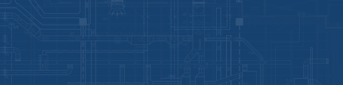
Simplex Switchgear Configuration
In the simplex switchgear configuration, the 4160V/600V, step-down transformer is connected to the switchgear via cable bus.
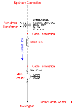
Parallel Switchgear Configuration
In the parallel switchgear configuration, the two step-down transformers in parallel are connected to switchgear busses A and B, respectively. Switchgears A and B are connected with the “tie” circuit breaker, in this case CB-1001T. The “tie” circuit breaker is normally open, whereas the “main” circuit breakers are normally closed during normal operating conditions. If for example, XFMR-1000A fails, then CB-1001A1 opens and CB-1001T closes, automatically. This will allow XFMR-1000B to provide power to both switchgears A and B and their corresponding downstream loads.
Note that in both the configurations above, We’ve assumed that each configuration is isolated. Meaning that the upstream and downstream connections to each configuration are 100% reliable.
Assumptions:
We will be assuming that one of the two configurations is required for of a 40,000 bpd, SAGD facility with a 30-year lifecycle. If the configuration fails, then the entire facility will fail.
Probability of correct operation for each configuration:
The probability that the simplex switchgear configuration will operate correctly is also known as its reliability. Therefore, Psimplex = Rsimplex.
We know that side A and side B are equivalent. We will assume that sides A and B operate independently and that their operating probabilities are independent events. Therefore, PA and B = PA*PB and PA = PB.
Therefore, the probability that the parallel switchgear configuration will operate correctly is Pparallel = PA + PB – PA and B. In terms of the simplex configuration, the probability of the parallel configuration is Pparallel = Rsimplex*(2 – Rsimplex).
Probabilities of Side A and Side B.
Failure rate of each configuration:
Based on the US Army’s reliability database [1], we can determine the failure rate for each piece of equipment as show in the following table:
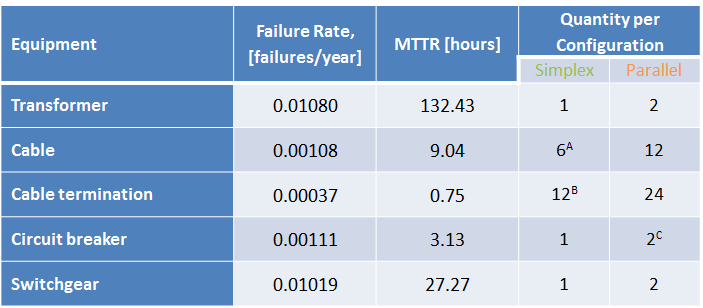
Equipment Failure Rates
A = Cable bus between the transformer and circuit breaker is assumed to be 3 phase, 750MCM, with 2 parallel runs. Therefore, the quantity is 6 = 3 phases * 2 runs.
B = Each cable will require a termination on the secondary of the transformer and the circuit breaker. Therefore, the quantity is 12 = 6 cables * 2 terminations.
C = We will only be including the 2 main breakers and ignoring the tie breaker.
We can replace the equipment in the simplex configuration with the equipment’s failure rate as follows:
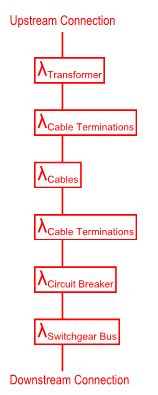
Simplex Configuration Failure Rates
Since the failure rates are in series, we can sum them to get λsimplex ≅ 0.03302 failures/year.
In a similar fashion, we can convert the equipment in the parallel configuration with its failure rates:
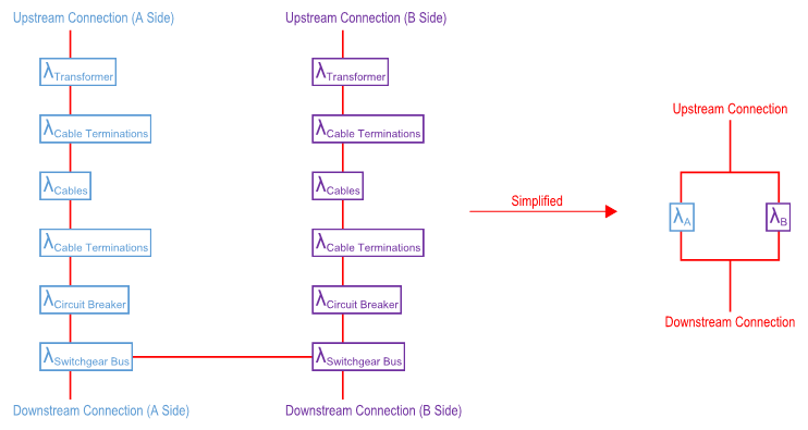
Parallel Switchgear Configuration Failure Rates
Note that for simplicity, we have assumed that the tie breaker, CB-1001T is 100% reliable; therefore, it has a failure rate of 0.
The failure rate of the parallel configuration is not as straight forward as the simplex configuration. To calculate its failure rate, we must first calculate the reliability of the system.
Reliability of each configuration:
The reliability equation for the simplex and parallel configurations will be as follows:
R(t)simplex = e-λsimplext
R(t)parallel = 2e-λsimplext – e-2λsimplext
As you can see from the following graph, the parallel configuration is 3 – 25% more reliable than the simplex configuration over a 30-year lifecycle.
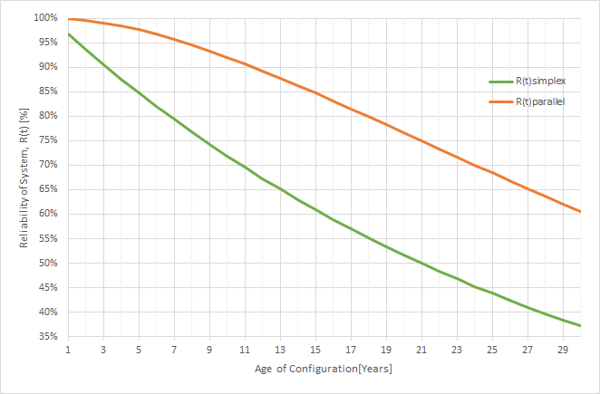
Difference in Reliability for the Simplex and Parallel Switchgear Configurations
We will now calculate the Mean Time Before Failure, MTBF = ∫R(t)dt
Therefore,
MTBFsimplex = 1/λsimplex ≅ 30 years/failure
MTBFparallel = 3/(2λsimplex) ≅ 45 years/failure
By definition, λ = 1/MTBF.
Therefore, λparallel ≅ 0.02201 failures/year.
Conclusions:
From the following table, we can see that the parallel configuration is 3 – 25% more reliable than the simplex configuration. Statistically, we can expect one failure with the simplex configuration during the 30-year lifecycle of our facility and less than one failure for the parallel configuration.
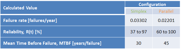
Summary of Failure Rates, Reliability and MTBF for the Simple and Parallel Switchgear Configurations
The reader should consider that each facility is unique and that there are many factors that we have ignored for the sake of simplicity that can affect the failure rate and reliability of the system, such as:
- Transmission/distribution line reliability
- Substation configuration
- Maintenance procedures
- Site generation
References:
[1] Department of the Army, “Survey Of Reliability And Availability Information For Power Distribution, Power Generation, And Heating, Ventilating And Air Conditioning (hvac) Components For Commercial, Industrial, And Utility Installations,” 22 July 2006. [Online]. Available: http://armypubs.army.mil/eng/DR_pubs/dr_a/pdf/tm5_698_5.pdf. [Accessed 19 November 2014].