
The sight of control blocks on a Piping & Instrumentation drawing (P&ID) may seem confusing and daunting for the uninitiated, but having some basic understanding of process control can help in deciphering these little black boxes of logic. The following series of articles aims to provide the reader with a brief overview of various control schemes typically encountered in industry complete with deconstruction and examples of application.
Industrial processes can be automated in various ways, typically by some measurement such as level, temperature or pressure and controlling some final element such as a control valve. The basic control loop in its simplest form would consist of a single measurement, a controller, and an output which usually is a control valve or another controller (more on cascaded loops later).
A controller can be as simple as an On-Off controller such as a household thermostat, however, most regulatory control in industry will require more dynamic control and therefore utilizes the Proportional-Integral-Derivative (PID) controller. A controller is tasked to monitor the current measurement (i.e., process variable or PV) as it deviates from setpoint (SP) and take corrective action based on this deviation. In the formula below, the control action u(t) or manipulated variable (e.g., valve action) is made up of various terms based on the deviation or error e(t), defined as e(t) = SP – PV.
Basic PID control algorithm. (Wikipedia)
Block diagram of a basic PID control algorithm. (National Instruments)
For the PID controller, the various tuning parameters are proportional gain, integral time, and derivative time.
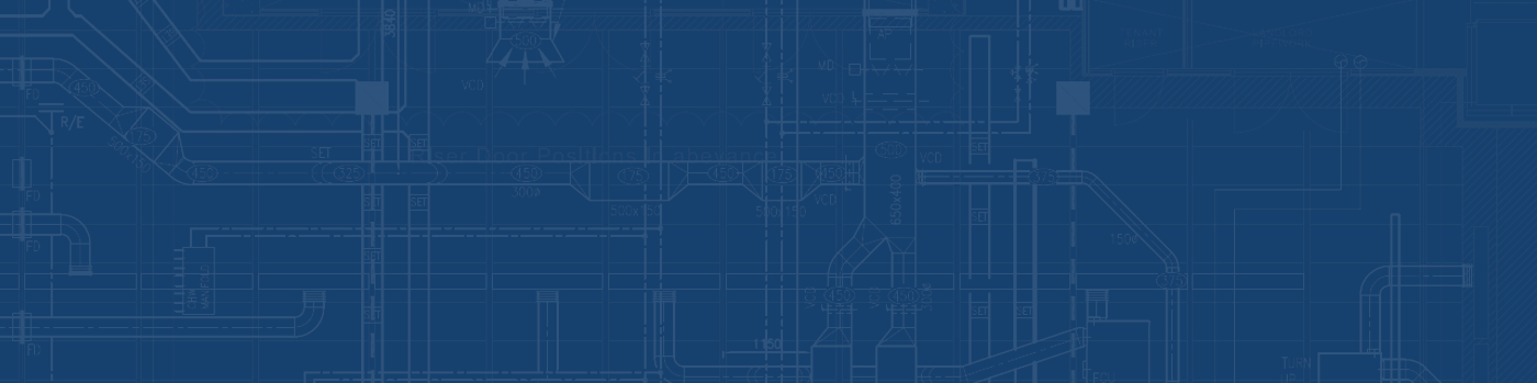
P-Action Controller (OptiControls)
- A proportional controller (i.e., P) can be a simple flow controller. When flow deviates from setpoint, the controller would make a valve output change to restore flow back in the direction of the setpoint equal to a multiplier of the flow deviation. The larger the multiplier, the more aggressive the controller action.
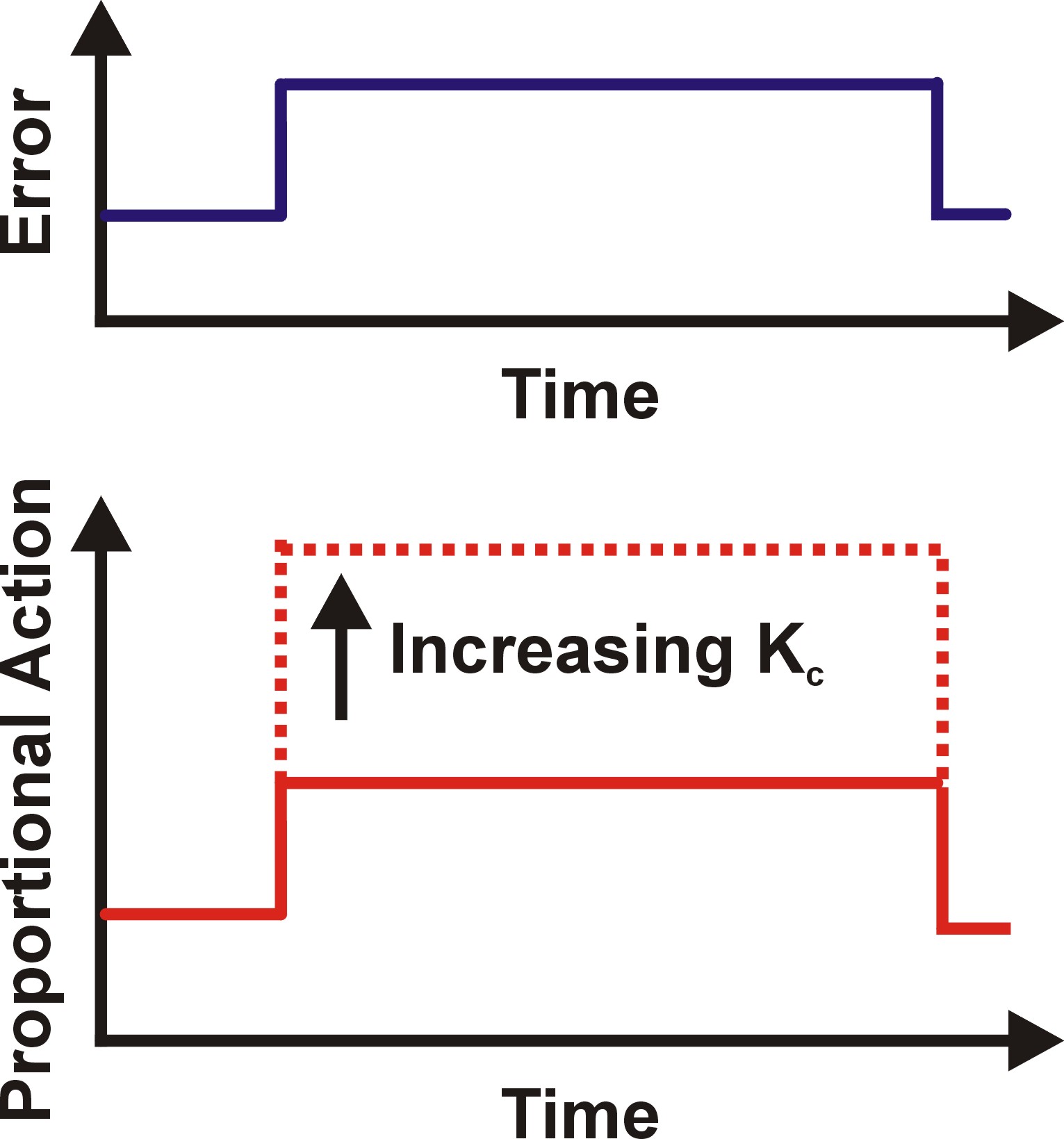
I-Action Controller (OptiControls)
- A proportional-integral controller (i.e., PI) can be thought of as a level control where changes in outlet valve position would cause a sustained change in tank level (e.g., outlet valve opens, tank level will drop and continue to drop until valve closes back to its original position). Any controller action will be based on the accumulated error (integrated error) from the setpoint over time. The larger the Integral time, the less aggressive the controller action.
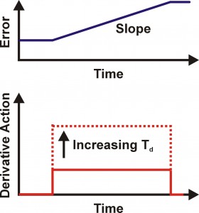
D-Action Controller (OptiControls)
- A proportional-derivative controller (i.e., PD) can sometimes be seen in slow-response systems such as furnace temperature to fuel gas control, where fast controller response would need to be based on the rate of change (i.e., derivative) of the deviation rather than a multiplier of the deviation itself (i.e., proportional control). The quick initial “kick” provided by the PD controller allows for a faster/more stable response than the purely proportional controller. The larger the derivative time, the more aggressive the controller action.
More complex controls can be achieved by setting the output of one controller (i.e., Primary or Master) as the setpoint of another (i.e., Secondary or Slave) in what is called Cascade Controls. The advantages of having two controllers is to try and control two related systems with different dynamic behaviour. A typical use would be to control the level in tank (a slow changing variable), while controlling the flow dynamics of the outlet flow (a fast changing variable). The advantage of a level to flow cascade controller over a level controller is that the flow controller is able to respond much faster to changes on the line (e.g., line pressure changes, etc.) than the level controller. Downstream disturbances can be quickly handled by the fast-acting flow controller before the level is impacted. A good case study can be seen here.

A typical level to flow cascade control scheme. (OptioControls)
NEXT on Part 2: More complex controls (Overrides and Ratio Control).
References
- “PID Controller“. Wikipedia. Retrieved 2014-03-30
- “PID Theory Explained“. National Instruments White Papers. 2011-03-29
- Smuts, Jacques. “PID Controllers Explained“. opticontrols. 2011-03-07
- Smuts, Jacques. “Level Versus Flow Control“. opticontrols. 2012-08-17