
The sight of control blocks on a Piping & Instrumentation drawing (P&ID) may seem confusing and daunting for the uninitiated, but having some basic understanding of process control can help in deciphering these little black boxes of logic. As a continuation of the last discussion regarding complex controls (high/low select, ratio, etc.), this discussion will further explain situations where multiple modes of operations or multiple control valves are utilized to control one property.
Multiple Controllers
In almost all PID-controller applications, a single measured value is typically being controlled and multiple manipulated variables (i.e., control valves, VFD speed setpoints, etc.) can be used to control the variable in question. The various examples of multiple controllers are not restricted to the examples below, but the following are illustrated here as a starting point for discussion.
Multiple Setpoints
In cases where multiple setpoints or different dynamics are needed for control, the most effective solution would involve multiple PID controllers setup with unique setpoints and tuning parameters. Examples include pump discharge flow with a minimum flow recycle controller where the minimum flow setpoint is different than the discharge flow rate, or vapour relief valve on a vessel where the relief valve action occurs at a higher pressure SP and needs to react much faster.
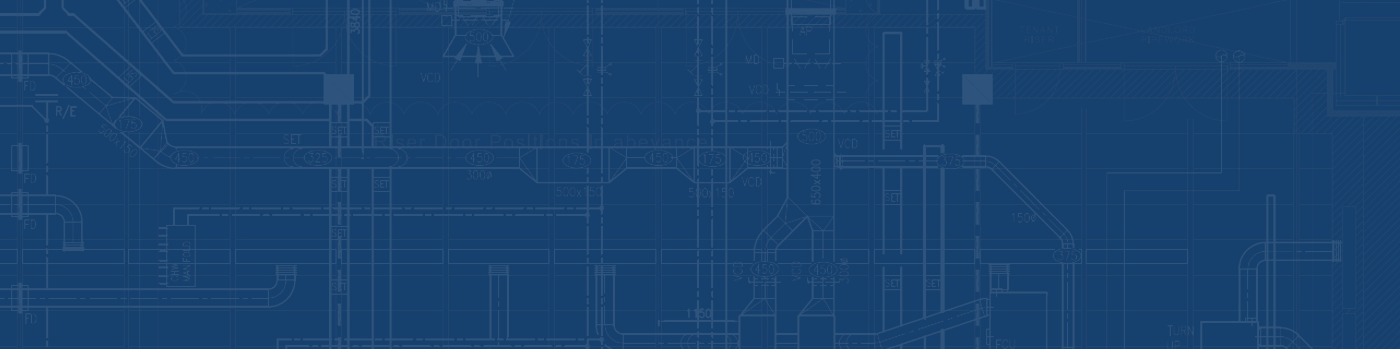
In the diagram below, normal vessel pressure is maintained by pressure controller PIC-01 as it bleeds off the vapour via valve PV-01. If however there is a blockage downstream and the vapour quickly builds up in this vessel, the second controller PIC-02 with a higher setpoint will start bleeding off the vapour via valve PV-02 to bring the vessel pressure under control.
Pressurized vessel with pressure relief
These two controllers behave more or less independently from one another even though they both utilize the same measurement. They provide the most versatility because valves can be different (i.e., sizes, valve characteristics – linear, equal percentage, quick opening, etc.) therefore dynamics can be different and controller tuning parameters will be unique between controllers. There are no restrictions, process conditions notwithstanding, on how far apart the setpoints can be set between the two controllers.
Split Range Control
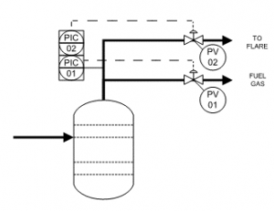
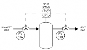
There are cases where multiple control valves are utilized in one control strategy, such as a tight pressure control of a vessel. The open and close positions of each valve are mapped to the total controller span and configured to be at different open states depending on the current controller output. This allows a tight band of control for the measured value by utilizing two control valves. The assumption is that the valves are of similar dynamics and controller tuning is consistent throughout the travel range of both valves. More discussion later on valve characterization.
Pressurized vessel on split range control
Valve outputs of two split range valves
Single-to-many Control
Although this is not an example of multiple controllers, there are situations where such a control is needed to control a discharge header, such as controlling header pressure downstream from several steam generators. This is a more simplistic control in that the control action is mirrored across all the control valves (Note: the actual implementation can be more complex at the final control element, either utilizing flow control cascade or adjusting firing rate of the steam generator).
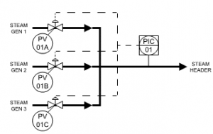
Header pressure control
Valve Characterization
The choice of valve used for control not only depends on the type of commodity/service, but also the characterization of the valve. Normally, valves used for control should behave more or less the same way over the travel range of the valve. The characterization of such a valve would be referred to as linear because the same controller gain could be utilized over the range of the valve. To say this another way, the valve output (which affects measured variable such as discharge flow) changes linearly with changes in the controller output.
To see this, let’s look at a butterfly valve used typically for discrete control (i.e., on/off control). Valve characterization is a plot between valve position and measured flow (or any other measurement that this valve will be used to control with). The sharp transition early in the valve position will greatly affect the tuning of the controller when operating at that flow rate versus if flow was higher (i.e. valve position is greater).
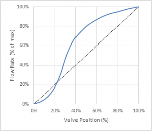
Valve characterization for butterfly valve
A plot of the stable controller gain of the flow controller versus valve position shows a drastic difference at the point when the valve transitions from close to open. Had this valve been commissioned as a flow control valve, there would be significant performance issues due to the large differences in operability the valve will go through as it transitions from open to close. This type of valve is better used in discrete control or as a shutoff service.
This is an extreme case but in certain applications where control valves plotted with the controlling measurement exhibit a non-linear valve characterization (e.g., pressure control), it is possible to linearize the valve and re-map controller output to the measurement in order to provide better control. Refer to the references below for further readings regarding some case studies in this topic.
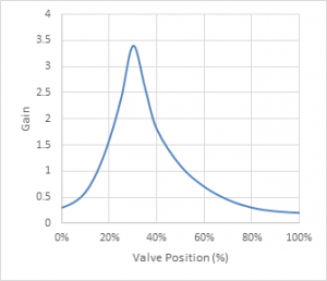
Gain plot of butterfly valve
This concludes the introductory series of PID control and their usage in industry. Hopefully, the preceding examples further highlight the versatility of the PID controller and its various applications in different scenarios. There are of course further more complex controls such as model-predictive controllers, and neural network technologies used in more complex facilities with fractionation and reaction processes. Discussions around the technology used to implement these control strategies are another topic that can be tabled. Stay tuned.
PREVIOUS on Part 1: Introduction to PID Control.
PREVIOUS on Part 2: Override, Ratio, and Bias Controllers.